


21 tick clock, so just over half a minute for a full length line! (Took 35 seconds per my stopwatch, that would include initialization time and other non-clock delays. Also includes any lag ;D)
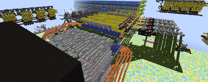
Machine can draw any straight line of positive slope in the first quadrant of a coordinate plane. All adders are 4-tick CCA, and all registers use repeater locks. The core of the algorithm is the counter variable. It is initialized to a value, and every turn it does the following:
Add 1 value
Subtract another value
If result of subtraction is negative: don't have subtracted it (this is done with a multiplexor, not another adder)
If result of subtraction is positive: increment Y
It loops this every cycle, also incrementing X every cycle.
If the line's slope is >=1, Y should be incremented every cycle and X should only increment when the counter overflows. To solve this, I have 3 multiplexors that switch the values of X and Y whenever dy/dx >= 1. (There is no divider in this machine. I never actually calculate the slope, but instead calculate dy - dx. If this result is positive, dy>=dx, which is the same thing as dy/dx >= 1). Before calculating whether to switch the variables, dy and dx are y1-y0 and x1-x0, respectively. After the switch, the definition changes. dx is whichever one is greater. If dx was originally less than dy, they've now been switched.
Finally, the machine has a single incrementer to determine when it's done. Instead of comparing the current X value to the target X value, I made an incrementer that adds 15 every cycle (same as subtracting 1 in 4 bit binary). It initializes to dx, so every turn it represents how far away it is from the target point (x1, y1). When it reaches a value of zero (which is conveniently also when the Cout of the adder is off), it stops the clock and cancels the signal being sent to the display so that the machine stops at the right point.
Speaking of the display, it's very simple. It uses 2 4-bit decoders for X and Y. The plot button acts as a line of AND inputs to the X decoder output so that nothing is plotted without it. I have a compact AND grid connected to SR latches so that the display never has to expand beyond 2x2 for each point. Very simple common design (droppers facing each other). Just for fun, I made this one with pistons and water, using barriers for a clean look.
The control room is the only room in the building lol. It's made of nether brick and pretty noticeable. There are 4 sets of 4 levers as well as 2 buttons. All are labeled. X0 and Y0 are the inputs for the first point, and X1 and Y1 are the inputs for the last point. The Start button initializes all registers and starts the clock while the Reset button clears the display and resets the clock. You can turn around and see the display. I tried to make the controls as self-explanatory as possible :)
Comments
Build image (didn't load properly)