


text file formatted with linebreaks available here:
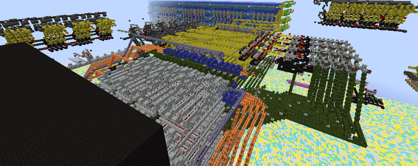
The Goat2 is a Harvard-architecture RISC machine, implemented as
a pipeline of 2-stages, running with a clock period of 26 ticks.
Due to the goal of keeping critical signals short, it might be better
described as a DPU (Distributed Processing Unit) as opposed to CPU!
Its internal registers are:
- a program counter register "P" (yellow near ROM) 2524/197/-2510
- an 8-bit accumulator "A" (red beside ALU) 2476/219/-2496
- an 8-bit pointer register "X" (purple behind RAM) 2519/219/-2450
- a "link" "L" to hold a return address (purple near Incrementor) 2507/195/-2493
- 2 single-bit flags: "Z" zero (blue), and "C" carry (red) (under ALU) 2491/197/-2479
Instruction words are 13 bits wide: 8 bits of data (white) and a 5 bit opcode (pink).
Depending on the instruction, the 8 bits of data is either a RAM address,
a literal constant, a branch target address in ROM, or otherwise ignored.
Instruction decoding is scattered everywhere along the (pink) inverted
opcode bus, with the decoding of interest close to where control lines are needed.
Although the instruction set supports full 8-bit address for both ROM and RAM,
I implemented only 56 instruction words of ROM and 16 bytes of RAM
for reasons of speed and plot size.
Therefore registers "P" and "L" implement only 6 bits each, and only the lower 4 bits
of register "X" are connected to the RAM address mux.
Clock (light blue) and reset (black) control are in front of the ROM and low.
2504/181/-2474
Explanation of Features
-----------------------
Indirection
-----------
The single pointer register "X" is used for all indirection.
To illustrate its use, here is a possible "memcpy" implementation:
memcpy:
ldx srcptr ; load X with current source pointer
ldax ; load source byte
ldx dstptr ; now load X with current destination pointer
stax ; store byte to destination
inc srcptr
inc dstptr ; bump both pointers
dec loopcount ; reduce count
jnz memcpy ; repeat for the length of the transfer
...
Delay Slots
-----------
Pipeline means the next instruction is fetched while the current one is executing.
When the current instruction is a branch or call or return,
the Goat2 will still execute the fetched instruction,
rather than discard it as some other CPUs do when a branch is taken.
(Goat2 is similar to SPARC in this regard)
Because no instruction is ever "wasted", the need for "branch prediction"
is completely eliminated for 2-stage pipeline computers.
A delay slot instruction is never skipped.
If you really can't think of anything useful, then put a "nop".
Call and Return
---------------
The Goat2 has no hardware stack or stack pointer. Instead, the "call" instruction
is actually a "jump-and-link" instruction: the return address is stored into
the link register "L", and the program counter "P" receives the target address.
(Similar to ARM Cortex behaviour).
This approach allows single-cycle dispatch to called functions.
Note: the return address is saved into "L" by the 2nd stage of the pipeline,
so it (correctly) contains the address AFTER the delay slot instruction.
The Goat2 offers three different "return" instructions:
retl
This loads "P" from "L" directly.
This is useful for simple functions which do not call other functions,
the return address simply stays in "L" and is returned to at the end.
ret <addr>
This loads "P" from the contents of memory address <addr>.
The called function should store "L" at some address using the
"stl <addr>" instruction somewhere near the beginning of the function.
This is an easy way to write non-recursive functions.
Note: ret <addr> can also be used to perform indirect jumps or computed goto.
retx
This loads "P" from the location pointed to by register "X"
Recursive functions must employ some kind of software stack;
one such implementation is as follows:
myfunction:
stl temp ; hold "L" temporarily
ldx stackpointer
lda temp ; get "L" back
stax ; store return address to whereever "X" points
inc stackpointer ; bump address (this example uses post-increment "push")
... ; do function work which may involve calls to myself
dec stackpointer ; un-bump (here we must pre-decrement for "pop")
ldx stackpointer
retx ; jump to the return address saved where x points to
... ;(delay slot) something useful like loading a return value
Register Forwarding
-------------------
As mentioned previously there are two stages in the pipeline which operate in parallel.
The first stage fetches instructions and arguments for the ALU.
The arguments are read midway through the stage after the instruction was fetched.
The second stage latches the ALU arguments and opcode from the first stage,
then performs ALU computation and prepares for the writeback of the ALU output.
The writeback actually occurs at the end of the stage (at the following clock edge).
Without register forwarding this produces surprising results;
consider the naive, pipeline-unaware code sequence
lda value1 ; load "A" from "value1"
aca value2 ; add-with-carry "A" and contents of "value2", result to "A"
sta result ; store sum here
The problems with this code (without forwarding) are:
- when the first stage is fetching the arguments for aca,
register "A" has still not been updated with the contents of value1 from lda.
- When reading "A" for sta, register "A" does not yet contain the result of the add.
What forwarding does is to connect the first stage's argument reader
EITHER to the present register output (if the register is not being updated),
OR directly to the alu output bus (if the register is being updated).
This connection is safe to make even if the ALU has not finished calculating output,
since the final value will only be latched at the (next) clock edge.
With forwarding, the naive example above works correctly as the comments indicate.
The Goat2 supports forwarding for registers "A", "X", and the two flags "Z" and "C" only.
But specifically, memory forwarding is NOT supported!
Examples such as this will still give surprising results...
sta temp ; write new value
lda temp ; !!this value of temp is the old value from before the sta!!
Instruction Set
---------------
There are 3 logical (or, and, xor) and 1 arithmetic (add-with-carry) instructions
which read and update the accumulator "A".
The second argument is either an immediate constant or a RAM address.
with these 4, software can create the rest: add (no carry), sub, sbc, complement, etc.
The 4 monadic operators (increment, decrement, rotate right, and ?reserved?)
operate on a single byte in RAM only.
All the above instructions affect the "Z" flag (Z=1 if ALU result is zero)
Adding, shifting, or rotating also affect "C" flag (C=1 if carry out is set)
All other instructions, including loading, storing,
and jump/call/return instructions never affect the flags.
(PLEASE VIEW TABLE IN FIXED-WIDTH FONT)
Instruction decoding table
--------------------------
top2 00 01 10 11
bot3
000 nop ori # inc m ora m
001 jl t ani # dec m ana m
010 jc t xri # ? m xra m
011 jnc t aci # ror m aca m
100 jz t mvia # sta m lda m
101 jnz t retl stl m ret m
110 jle t mvix # stx m ldx m
111 jgt t retx stax ldax
t = a target (ROM) address
# = a numeric constant
m = a memory (RAM) address
jle = jump if either carry or zero is set
jgt = jump if both carry and zero are not set
? was originally rol, or rotate left
but it seems such a waste because the sequence
lda m, aca m, sta m produces the same output in memory and carry,
whereas there is no substitute for ror (it can divide by 2).
Also, without memory forwarding, a sequence of rols or rors
on the same address does not do the expected useful thing.
For now, this instruction spot is reserved for a better idea not described here
Single-Step & Breakpoints
-------------------------
Breakpoints are added by placing repeaters in the topmost (red) level of ROM.
There is no limit to the number of breakpoints set.
When the selected ROM is read, the system clock will stop
and the note block at 2515/190/-2472 will play.
To continue normal execution at full speed again,
press the Single-Step button once.
It is not necessary to remove the breakpoint; this is
useful for stopping at the same point in each iteration
of a loop for example.
If instead you wish to single-step the next few instructions,
first stop the clock, then press Single-Step.
Only 1 instruction will execute for each press of Single-Step.
To resume full speed operation when not stopped at a breakpoint,
just turn the clock back on.
Demonstration Program: Double Dabble
------------------------------------
The demo program is an implementation of the well-known DoubleDabble algorithm
which converts a binary byte into BCD.
It illustrates many of the Goat2 features:
calling functions
different types of return
conditional branching
delay slot instructions
indirection
register forwarding
To use the demo, there is a (magenta) column of levers 2470/216/-2447
for the input byte inside one corner of the RAM (cell 0xf)
and 3 decimal digit displays designed by Cadenjb
attached outside the orange ALU output bus. 2449/217/-2502
The levers presently have a value of 0xA5 = 165 decimal.
Enter a binary number on the levers and start the computer (see below).
Let it run for about 25 minutes to view the result.
Reset/Restart Procedure
-----------------------
- Turn on RESET
- Turn on CLK
- Wait at least 2 full periods
- Turn off RESET
The program execution begins at ROM location 0,
All registers and flags are considered garbage
and should be initialized by software before use.
Although the clock will automatically shut off
due to a breakpoint I left at the end address 3,
it is polite to turn off the CLK when you are
finished using the computer.
Demo Program Listing
------------------------------
Program Listing: Double Dabble
------------------------------
// RAM addresses used:
#define input 0x0E // memory mapped levers
#define units 0x0F // top nibble drives lamps
#define tens 0x0D // top nibble drives lamps
#define hundreds 0x0B // top nibble drives lamps
#define binary 0x0C // copy of levers, consumed during execution
#define binret 0x0A // return address for toplevel
#define loopcnt 0x09 // iteration downcounter
#define tmp2 0x02
#define tmp1 0x01
#define call jl // call is an alias for the jump-and-link instruction "jl"
#define jmp jl // so is jmp
// we use call to show we expect the called function to return
// whereas we use jmp to show an unconditional jump with no return
// but remember "L" is overwritten no matter which alias is used!
// timing information cycle count: 1~ = one instruction
// 535~ * 2.6 seconds/~ = 1391 seconds, or 23 min 11 seconds.
program:
00 1c0e lda input ; read levers
01 0105 call bin2dec
02 140c sta binary ; (delay slot) store input argument
done:
03 0103 jmp done ; loop forever
04 0000 nop ; (delay slot)
; this routine converts the value stored in "binary"
; into the top nibble of 3 bcd bytes named units, tens, hundreds.
bin2dec: // 11~ + 8*65~ = 531~
05 150a stl binret ; save return address
06 0c00 mvia #0
07 140f sta units
08 140d sta tens
09 140b sta hundreds ; clear output variables
0a 0c08 mvia #8 ; we loop 8 times...
0b 1409 sta loopcnt ; because "binary" contains 8 bits
0c 0b00 aci #0 ; clear carry (add 0 to "A" with carry yields no carry)
0d 1c0c lda binary
ddloop: // 11~ + 3*18~ = 65~ for one iteration of the loop
0e 1b0c aca binary ; shift left (add to itself), msbit goes to cy
0f 140c sta binary
10 011b call dd ; do double-dabble on this digit
11 0e0f mvix #units ;(delay slot) point to units variable
12 011b call dd
13 0e0d mvix #tens ;(delay slot) point to 10s
14 011b call dd
15 0e0b mvix #hundreds ;(delay slot) point to 100s
; maximum hundreds value of 2 never overflows so carry is always clear
16 1109 dec loopcnt
17 050e jnz ddloop
18 1c0c lda binary ; (delay slot) get ready to double in next iteration
19 1d0a ret binret ; return to caller
1a 0000 nop ;(delay slot) nothing useful to put here
; this is double dabble on a single bcd digit.
; the 4 bits of digit are in the top nibble of the byte
; therefore, to add 3 we really need to add 0x30
dd: // 18~
1b 031e jnc savecy
1c 0c00 mvia #0 ; (delay slot) we will save this value if input carry was 0
1d 0b0f aci #0x0F ; otherwise we will save 0x10 (cy + 0x0F)
; note: this also clears carry
savecy:
1e 1401 sta tmp1 ; save shifted input cy here (0x00 or 0x10)
1f 1f00 ldax ; get bcd digit (high nibble)
20 0b30 aci #0x30 ; trial add 3
21 1402 sta tmp2 ; save result of trial addition here
22 0980 ani #0x80 ;if bcd digit was originally 5 or more, then bit 7 will now be set
23 0526 jnz double ; if result after AND is non-zero, this means bit 7 is set
24 1c02 lda tmp2 ;(delay slot) re-get trial result on our way there
25 1f00 ldax ; re-get original bcd digit since it was less than 5
double:
26 1402 sta tmp2 ; this is what we want to double
27 0b00 aci #0 ; but first we clear carry
28 1c01 lda tmp1 ; get (shifted) input carry
29 1b02 aca tmp2 ; *1
2a 1b02 aca tmp2 ; *2
2b 0d00 retl ; return to caller (output cy goes to the next higher digit)
2c 1700 stax ;(delay slot) store the updated bcd digit as we leave
Program size: 45 instructions ROM.
From 56 leaves 11 instruction words unused (empty).
Data size: 9 bytes used.
From 16 leaves 7 bytes unused.
Comments
Notice to evaluator(s)
Since 1.16, the MC client is swamped with light update messages when the computer runs.
To see this pipeline computer running, you could export a .schematic of it and drop it into a 1.15.2 world
(which was when this promo request was submitted). I don't know if it will run in a single-player 1.16 world.