
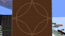
Circle Itself
I built a circle drawer using a simplified version of the Bresenham circle algorithm, called the Midpoint alg.
A circle is defined by the equation x^2 + y^2 = r^2. This means that every point on the circle is at the same distance (the radius) from the center. When drawing a circle on a pixel grid, we can’t place points perfectly on that curve, so we approximate it by choosing pixels that stay as close as possible to that ideal equation.
The midpoint circle algorithm is a way to do this efficiently. Instead of checking every possible point, it builds the circle step by step using symmetry. A circle can be divided in equal parts an infinite amount of times. However that isn't the case for a pixelized circle. This one can be divided 3 times to create 8 symmetrical parts (octants), so the algorithm only needs to calculate points for one part of the circle and then mirror them to draw the rest. The algorithm that I used stays in octant 0.
Circle Algorithm
The algorithm starts at the point r, 0 and moves upward. At each step, it always increases y by 1. The x value sometimes stays the same, and sometimes decreases by 1. This creates a curve that follows the shape of the circle.
But how does it know when to decrease x? This is done using an error value (I used t1 and t2). These values track how far the current pixel is from the true circle. If the algorithm detects that it has gone too far outward, it corrects by moving one step inward (decreasing x).
Because the slope of the circle changes, this behavior makes sense:
At the start, the circle is steep, so it mostly moves upward (increase y).
As it approaches 45°, the curve becomes more diagonal, so it occasionally moves left (decrease x).
The alg stops when x < y, which means we’ve reached the 45° line.
Jesko’s method is a simplified version of this idea. It reduces the number of calculations per step by keeping everything incremental instead of having to multiply. So instead of recomputing the circle equation each time, it updates values using additions and subtractions. This makes it very efficient, especially for redstone.
Step by Step Explanation
Jesko's version of the Midpoint algorithm:
x = r

y = 0

Repeat Until x < y

    Pixel (x, y) and all symmetric pixels (8 times)

    y = y + 1

    t1 = t1 + y

    t2 = t1 - x

    If t2 >= 0

        t1 = t2

        x = x - 1
We start off by setting y to zero, x to the radius and clearing t1. Every clock cycle y increases by 1, we simply have to determine whether to keep x the same or decrease it by 1.
Then we update the accumulator t1 = t1 + y. This tracks how far we’ve moved relative to the ideal circle.
After that, we calculate a temporary value: t2 = t1 - x. This is the key decision value.
If t2 >= 0 (positive), it means we’ve drifted too far outside the circle rim. So we correct by moving inward: x = x - 1 and update the error: t1 = t2
If t2 < 0 (negative), we are still inside the circle, so: x stays the same, t1 remains unchanged.
Finally we send out X, Y to get plotted. If we fiddle a little it'll be easy to mirror this coordinate.
If we make Y negative: X, -Y we get the coord in the 7th octant and by swapping x and y: -Y, X we get the 2nd octant. This can be done for all 8. Also, the midpoint we're mirroring around needs to be 0,0.
The Display
So far, the circle drawer could only draw circles centered at 0,0, with the radius as the only input. This means every circle was always positioned in the middle of the display.
To make this more flexible, I added two new inputs: Xcenter and Ycenter. These let us move the midpoint of the circle anywhere on the screen instead of being fixed at the origin.
Originally, the coordinate system ranged from -31 to 31. To position the circle, you would take the coords generated by the symmetry logic and add the Xcenter and Ycenter offsets. This works but it adds unnecessary stuff because negative values require a sign bit, which complicates the hardware.
To simplify things, I changed the coordinate system to use only positive values, from 1 to 63. Functionally, this is the same range, but avoids dealing with negative numbers entirely.
To make this work, I shift all coordinates by a constant offset. Since the original range is centered around zero, I add 32 (half the screen width) to everything. The final screen position becomes:
32 + Xcenter + X
32 + Ycenter + Y
This remaps the coordinate system so that 0,0 is now in the middle of the screen, but all values remain positive. I first tried adding 31 instead, but that caused the range to go from 0 to 62. This was a problem because 0 is always true in the display, meaning pixels at that position would always be drawn.
I could have made the input a 6bit number from 1-63 but that makes it hard to find the center and drawing shapes at an equal distance from the edge or center. Opted for having 0,0 in the middle so you could flip the sign bit to for easy symmetry. And yes, you input from -31 to 31, then the screen converts it to 1 to 63 to then get converted back to -31 to 31 cause of the algorithm. Turns out that was the easiest for the display and for the user.
For example the point (10, 10) and X,Ycenter (5, -30):
32 + Xcenter + X -> 32 + 5 + 10 = 47
32 + Ycenter + Y -> 32 + (-30) + 10 =12
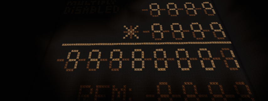
INPUTS
Input panel has 3 vertical binary inputs: The length of the radius, the x and y coordinates of the center point.
3 basic inputs: draw, stop and clear (clear is fully synchronized).
A selector panel featuring 3 shapes: circle, square and diamond. Only one can be selected at a time. (square works by keeping x constant by blocking the t2 output from updating x) (diamond works by always updating x. I overflow t2 to always be positive).
Finally it has 4 additional features which include:
- Disable drawing the center point (I block the X/Ycenter value -> 0 so it puts the center at 0,0 which is off screen. Whilst it's drawing I disable this with some precise timings)
- Rotation: draws the parts of a shape that go off-screen on the opposite side or in the other corners
- True 0,0 center coordinate (used with rotation): allows drawing four equal quarters in each corner by placing the center off-screen (bottom left corner)
- Improved visual quality: some circles may be mathematically correct but look off to the human eye. Enabling this uses a rom lookup table with custom values to adjust t1 during initialization. For example, for r = 8 the normal output looks like an octagon, so a correction of +3 is applied to t1. This feature is optional and not part of the original algorithm
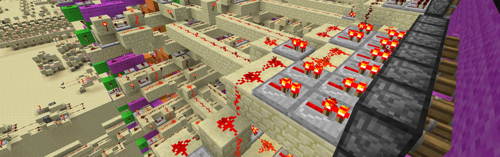
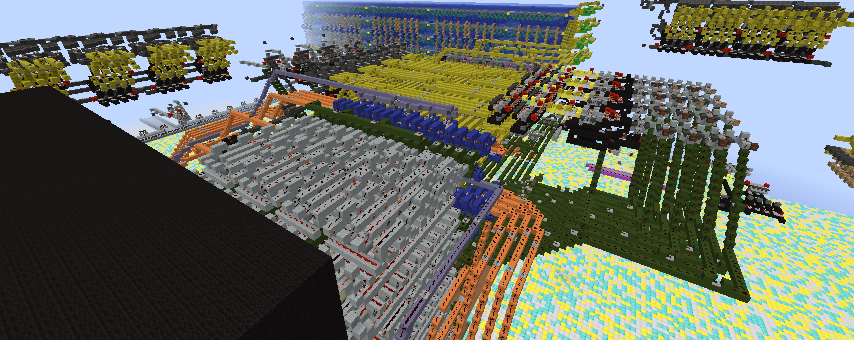
Better View of the Wiring
On the left of my circle drawer is a naked version that isn't blocked by the display itself, I made the extra wiring transparent and added a layout and brief explanation of each hardware circuit above.
Extras
- The drawer takes a 5-bit input but produces a 6-bit output, so I refer to it as 6-bit
- It is fully solid state
- Uses Don Manuel's 3t CCA
- I believe this deserves a rankup not just for complexity, but for the in depth explanation, the uniqueness of the project, and especially the size of the wiring
- I highly value compactness and speed. It runs at 2.5hz (1 pixel every 4 redstone ticks)
My explanation is a bit long but I hope that everyone learned something new :)
Comments
no shift
jesko's alg originally had a shift r << 5 at the start, but as the largest radius input is 31 and dividing any r by 32 will never be greater than 1. 31/32 = 0.97 as we're comparing it to whole numbers this is useless and I scrapped it.